Normally in electroplating, the hydrogen generation of the cathode causes hydrogen to penetrate on the materials.
In the case of galvanization, a certain amount of time passing after hydrogen penetrates into the inside of the iron.
If iron contains hydrogen, it may lose ductility and become vulnerable, so iron may break, shattar, or crack to exist.
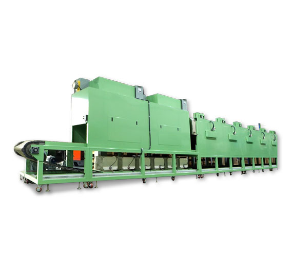
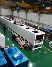
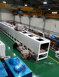
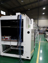
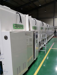
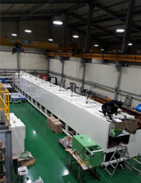
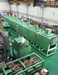
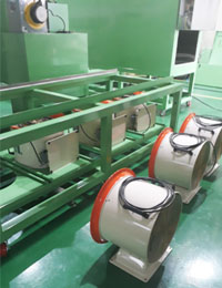
Hydrogen Embrittlement Relief Oven is equipment that produce as perfect and superior products by removing these hydrogen from materials or components.
Advantages of tunnel type!
In general, materials or components that have completed the electroplating and galvanizing processes should be baking within short time to remove hydrogen.
However, after completing the manufacturing process on the production line, Batch Type must wait a certain amount of time to process baking.
But, Tunnel Type has the advantage of being able to connect with the final line of the production line and do baking process mi mediately after completion of the manufacturing process.
So, because it removes hydrogen perfectly within short time, it produces high quality products.
Recently, automotive, ship and heavy equipment manufacturers have preferred the Tunnel Type, due to it has this advantage.
This is a global trend.
We have a performance of deliveries to leading Korea conglomerates and well-known foreign companies and are recognised for their quality.
Features
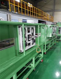
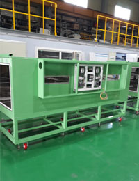
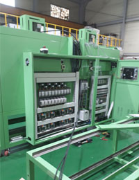
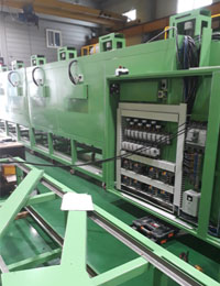
1. By using Digital P.I.D temperature controllers provides excellent temperature precision, and can be freely set temperature raising and temperature maintenance.
2. The PID Controller is a multifunctional temperature controller with built-in precise temperature control, Timer, Alarm, Auto Tuning, etc. and display the set temperature (SV), present temperature (PV) at the same time.
3. Auto Tuning : It is an operation function that calculates the PID integer required for optimal control by measuring the thermal characteristics and thermal response rate of various controlled objects on its own, and sets the value produce fast response and stability.
4. The temperature distribution is uniform and the drying time is fast as the air inside the chamber is forced to circulate by the sirocco fan.
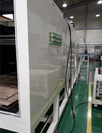
5. Perfect double insulation treatment prevents internal heat from being transferred to the external. Offering even temperature distribution, perfect and safe design.
6. The height of the shelf can be adjusted and additional shelves can be ordered.
7. Time range selectable(4 digits) → 99Hr59Min, 99Min59Sec, 99Day99Hr
8. Computer Connection
